
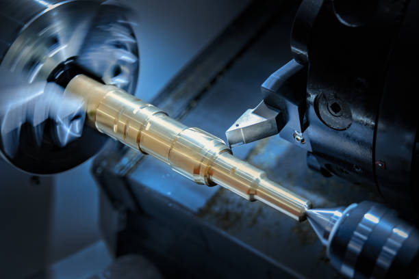
CNC machining center
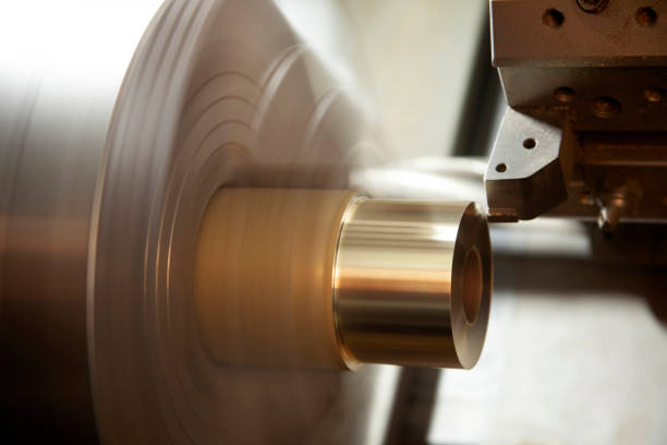
Traditional mechanical processing is the use of manual operation of ordinary machine tools, machining with hand shaking mechanical cutter cutting metal, by the eye with calipers and other tools to measure the accuracy of the product.Modern industry has long used computer-controlled machine tools for operations, CNC machine tools can be prepared in accordance with the technical personnel in advance of the program of any product and parts directly processed.This is what we call "CNC machining".Numerical control machining is widely used in all mechanical processing in any field, but also the development trend of mold processing and an important and necessary technical means.
'CNC' is an abbreviation for Computerized Numerical Control.
What is Numerical Control technology, Numerical Control technology, Numerical Control for short.It is a method to control machine tool motion and machining process by using digital information.The machine tool that implements processing control with numerical control technology, or the machine tool that is equipped with numerical control system is called numerical control (NC) machine tool.Numerical control system includes: numerical control device, programmable controller, spindle driver and feed device, etc.Numerical control machine tool is machine, electricity, hydraulic, gas, light highly integrated products.In order to control the machine tool, it is necessary to use geometric information to describe the relative motion between the tool and the workpiece and to use process information to describe some process parameters that the machine tool must have.For example: feed speed, spindle speed, spindle positive and negative rotation, tool change, coolant switch, etc.These information according to certain format form processing file (that is, the normal said the nc machining program) in the information carrier (such as disk, paper tape, tape, etc.), and then by the machine tool numerical control system to read (or directly through the numerical control system keyboard input, input) or by means of communication, through the decoding, to make the machine movement and machining parts.The modern numerical control machine tool is the typical product of mechatronics, and it is the technical foundation of the new generation of production technology and computer integrated manufacturing system.The development trend of modern CNC machine tools is high speed, high precision, high reliability, multi-function, complex, intelligent and open structure.The main development trend is to develop intelligent and full-function general numerical control device with open structure of both hardware and software.Numerical control technology is the basis of machining automation and the core technology of numerical control machine tools. Its level is related to the national strategic position and reflects the level of the comprehensive strength of the country.It develops with the development of information technology, microelectronics technology, automation technology and detection technology.CNC machining center is a CNC machine tool with a tool storehouse and can automatically change the tool, the workpiece can be in a certain range for a variety of processing operations.In the processing center processing parts are characterized by: processed parts after a clamping, CNC system can control the machine tool according to different processes automatically select and replace the tool;Automatically change the machine spindle speed, feed and tool relative to the workpiece movement track and other auxiliary functions, continuously on the workpiece processing surface automatically for drilling, shaving, reaming, boring, tapping, milling and other processes.Because the machining center can be centralized, automatic to complete a variety of processes, to avoid the artificial operation error, reduce the workpiece clamping, measurement and machine adjustment time and workpiece turnover, handling and storage time, greatly improve the processing efficiency and processing accuracy, so it has good economic benefits.Machining center according to the position of the spindle in space can be divided into vertical machining center and horizontal machining center.Horizontal machining center effectively solves the processing of large molds.
There are many kinds of CNC lathe, vertical CNC milling machine, horizontal CNC milling machine, and machining center......
CNC machining center system: OKUMA system and FANUC system, Mitsubishi system, Hyde Han, Rhodes, etc
The characteristics of
Compared with ordinary machine tools, CNC machine tools have the following characteristics:
● High machining accuracy, with high processing quality;
● Can be multi-coordinate linkage, can process complex shapes of parts;
● machining parts change, generally only need to change the numerical control program, can save production preparation time;
● Machine tool itself high accuracy, rigidity, can choose the favorable processing amount, high productivity (generally 3~5 times of the ordinary machine tool);
● Machine tool automation is high, can reduce the labor intensity;
● mass production, product quality is easy to control;
Disadvantages
Low quality requirements for operators, high technical requirements for maintenance personnel.
● But its processing route is not easy to control, not as intuitive as ordinary machine tools.
● The maintenance is inconvenient, high technical requirements;
● The process is not easy to control.
CNC machining center in several groups of commonly used instructions
A, pause instruction G04X (U) _/P_ refers to the cutter pause time (feed stop, spindle does not stop), address P or X after the value is the pause time.Values after X should have a decimal point, or they should be calculated as thousandths of the value, in seconds (s), and values after P should not have a decimal point (integer representation), in milliseconds (ms).For example, G04 X2.0;Or G04 X2000;Pause for 2 seconds G04 P2000;However, in some hole system processing instructions (such as G82, G88 and G89), in order to ensure the hole bottom roughness, when the tool processing to the hole bottom need to have a pause time, this time can only be expressed with address P, if the address X is expressed, the control system that X is the X-axis coordinate value for execution.For example, G82X100.0Y100.0Z-20.0R5.0F200P2000;Borehole (100.0, 100.0) to hole bottom pause for 2 seconds G82X100.0Y100.0Z-20.0R5.0F200X2.0;Drilling (2.0, 100.0) to hole bottom does not pause.
M00 is the unconditional suspension instruction of the program.When the program is executed, the feed stops and the spindle stops.To restart the program, you must first go back to the OG state, press CW (spindle forward) to START the spindle, and then go back to the Auto state, press Start key to START the program.M01 is the selective pause instruction for the program.The program must open the OP STOP key on the control panel before execution. After execution, the effect is the same as M00. To restart the program, same as above.M00 and M01 are often used to check the size of the workpiece or chip removal during processing.M02 main program end instruction.When this instruction is executed, the feed stops, the spindle stops and the coolant shuts down.But the program cursor stops at the end of the program.M30 main program end instruction.The function is similar to that of M02, except that the cursor returns the program header, regardless of whether there are any other program segments after M30.
Tool compensation parameters D and H have the same function and can be arbitrarily interchanged. They all represent the address name of the compensation register in the numerical control system. However, the specific compensation value is determined by the compensation number address behind them.However, in the machining center, in order to prevent errors, the general provisions of H for the length of the tool compensation address, the compensation number from 1 to 20, D for the radius of the tool compensation address, the compensation number from 21 (20 knife library).For example, G00G43H1Z100.0;G01G41D21X20. 0 y. 0 f200;
Four, mirror instruction mirror processing instruction M21, M22, M23.When only X axis or Y axis is mirrored, the cutting sequence (forward milling and reverse milling), the direction of tool complement and the direction of arc interpolation will be contrary to the actual program. When X axis and Y axis are mirrored at the same time, the sequence of tool complement and the direction of arc interpolation will remain unchanged.Note: after using the mirroring instruction must use M23 to cancel, so as not to affect the later program.In G90 mode, the use of mirroring or cancel instructions, will be back to the origin of the workpiece coordinate system can be used.Otherwise, the numerical control system can not calculate the movement trajectory behind, there will be disorderly knife phenomenon.At this time must implement the manual origin return operation to solve.The spindle steering does not change with the mirror command.
In the XY plane, the format is as follows: G02/G03X_Y_I_K_F_ or G02/G03 X_Y_R_F_, where X and Y are the coordinates of the end point of the arc, I and J are the increment values from the beginning point of the arc to the center of the circle on the X and Y axis, R is the radius of the arc, and F is the feed.In arc cutting, note that Q ≤180°, R is positive;q>180 degrees. R is negative;I, K can also be specified by R, when both are specified at the same time, R instruction priority, I, K invalid;R cannot do round cutting, round cutting can only be programmed with I, J, K, because there are an infinite number of circles with the same radius passing through the same point.When I and K are zero, it can be omitted;No matter G90 or G91, I, J and K are programmed according to relative coordinates;For arc interpolation, the knife cannot be used to fill the instruction G41/G42.
G54 ~ G59 is the coordinate system set before processing, while G92 is the coordinate system set in the program. If G54 ~ G59 is used, it is not necessary to use G92 again, otherwise G54 ~ G59 will be replaced, which should be avoided.Note :(1) Once G92 has been used to set the coordinate system, using G54 ~ G59 will have no effect, unless the system is restarted by power off, or the required new workpiece coordinate system is set by G92.(2) After the program of using G92, if the machine tool does not return to the origin set by G92, the program will be started again, and the current position of the machine tool will become the new coordinate origin of the workpiece, which is prone to accidents.Note: Confirm whether zero is set before each procedure.So, hopefully, use it with caution.
Basic parameters of CNC machining center
1. Stroke X Axis Stroke 800 MMY Axis Stroke 500mmZ Axis Stroke 500mm
2.Spindle spindle speed 8000/ R.P.M Spindle specification BT-40 spindle nose end to the work table distance 110-610mm Spindle center to the column rail surface distance 560mm
3. Fast displacement of feed X,Y and Z axes is 30,000/30,000/18000mm /min
4. Worktable size 1000*500mm maximum load 650KGT type groove number/size 5 * 18mm
6. CNC system Mitsubishi M70A
7. Tool library (standard tool library capacity 24 (arm type tool library) maximum tool diameter, maximum tool length, maximum tool weight
CNC machining center standard attachment
* Toolbox * Spindle blowing * Rigid tapping * Electric box heat exchanger
* explosion-proof working lamp * belt drive * program storage * fully closed protective cover
* External hanging handwheel * DNC computer transmission line * three-color warning light * three-axis screw pre-pull device
* Cutting cooling unit * Operation and maintenance manual * Automatic lubrication system
* Cutting blowing device * Horizontal bolt and pad * Triaxial telescopic cover
CNC machining center commonly used accessories
Name origin brand manufacturer
Main structure cast iron (bed) China adopts high strength cast iron
CNC controller Mitsubishi Mitsubishi/Fanuc FANU
Spindle drive motor Mitsubishi Mitsubishi/Fanuc FANU
Three-axis drive motor Mitsubishi Mitsubishi/Fanuc FANU
Spindle drive belt Spindle matching Luo Yi/National Taiwan University
Taiwan Xutai Spindle/Luo Yi/National Taiwan University (optional brand)
X, Y, Z Ball Screw Taiwan/Germany Yintai/Rexroth
Ball screw fixed bearing Japan/Germany NSK/FAG
Spindle bearing Japan/Germany NSK/FAG
X, Y, Z axis stick plastic American chardonnay board
Taiwan Line Rail Taiwan/Germany Yintai/Rexroth
Taiwan Shengjie Dao Database/Beiju Dao Database/Deda Dao Database (optional brand)
Contactor Schneider France
Overload protector schneider France
Total power switch schneider France
Solenoid valve switch Taiwan yadeke
Pressurized cylinder Taiwan Shengjie/Beiju/Haocheng
Cooling water pump China Luokai
Automatic lubrication system for Sino - Japanese joint venture river valley
Connector Germany R+W bellows expansion sleeve/LENS LS
The shield is interesting in Taiwan
1, Two line one hard CNC machining center X, Y, Z three axis stroke: 1000×600×600mm.
2, The main shaft transmission mode is belt type, the highest speed: 8000RPM (standard), according to the customer's requirements can be optional directly connected spindle 12000RPM / 15000RPM.
3, according to the needs of users to choose: CAM 20 knives fast ATC, or knife arm 24 knives absolute ATC, to meet the needs of different customers.
4. The head group is a heavy box structure.Internal rib reinforcement, high rigidity.
5, the spindle cutting tool adopts oil pressure mechanism, the spindle force is uniform when cutting tool, prolong the bearing life.
6, the electrical box adopts internal isolation design, the heating source part of the controller is separated, the front use of heat exchanger heat dissipation, to avoid external dust into the electrical box;A fan is used on the rear side to dissipate heat from the fan hot plate.
7, Three axis adopts high precision ball screw, combined with precision nut preloading and tail prepulling device, to ensure that the machine backgap and thermal deformation for a long time to maintain a low value.
8. Linear slide rails are used for X and Y axes, with a fast moving speed of 24m/min; hard rails are used for Z axis, with a fast moving speed of 18m/min. Three-axis chip feed of 8/8/8 (m/min) provides high-speed and stable cutting feed.
9, X, Y axis using linear slide rail, Z axis using hard rail, with high rigidity, low noise, low friction, can do fast displacement and obtain the best circulation accuracy.
10. All finished products have gone through laser positioning and rectification and circular testing.To ensure the best positioning accuracy and servo characteristics.And the machine before shipment after strict inspection measures, to ensure that the accuracy of the machine long-term stability.